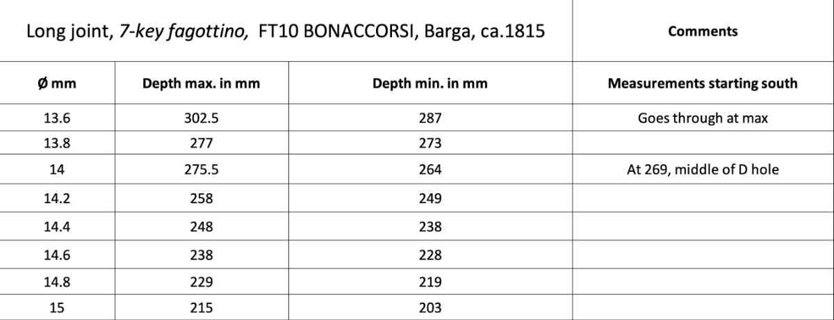
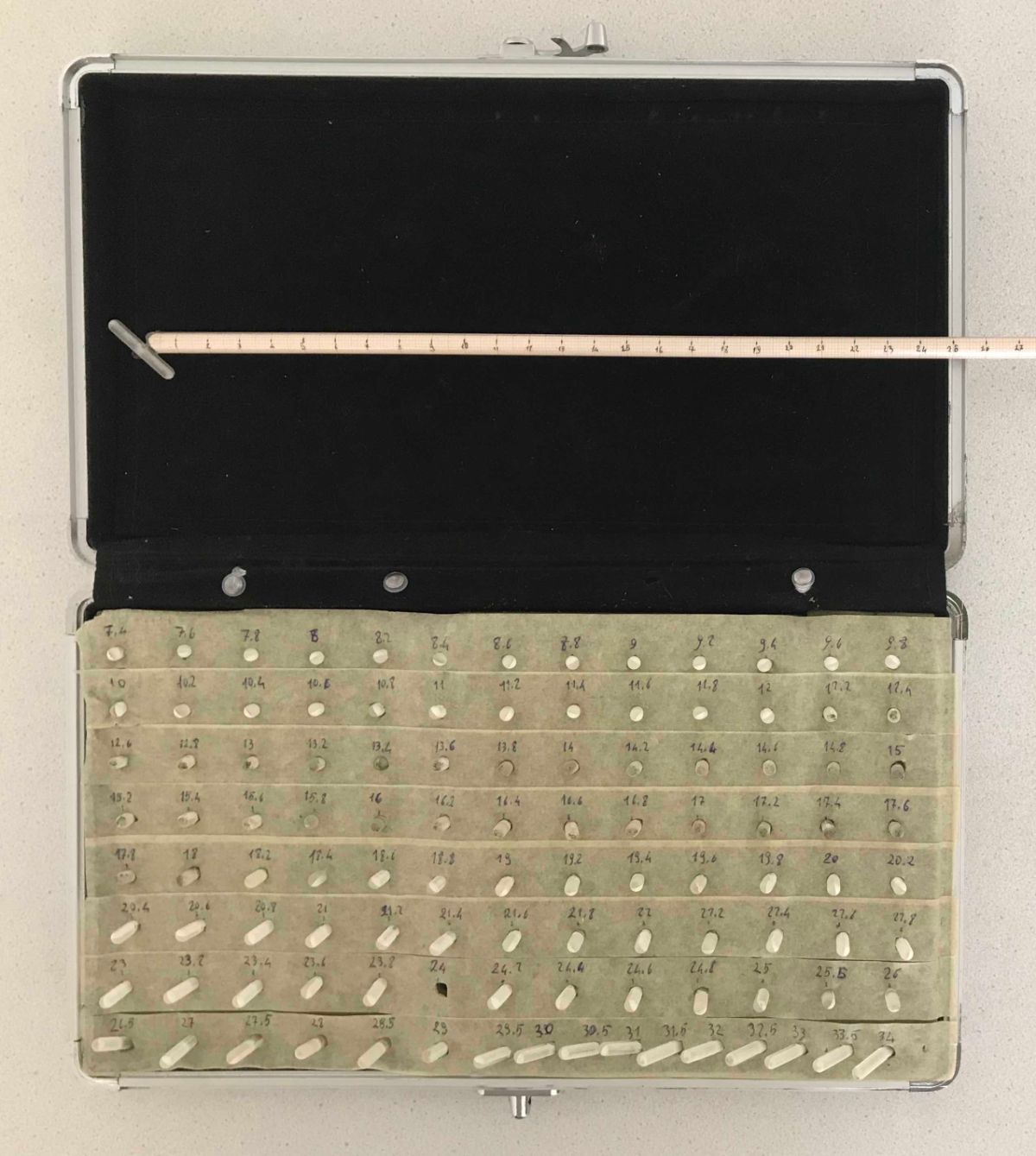
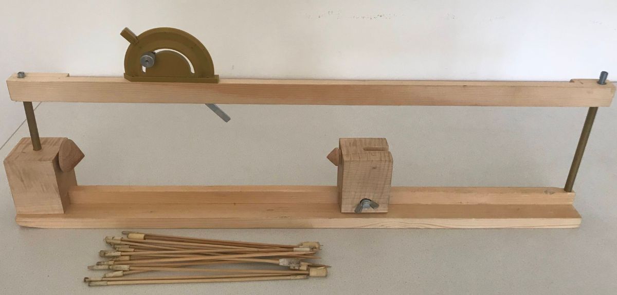
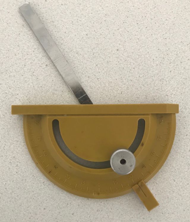
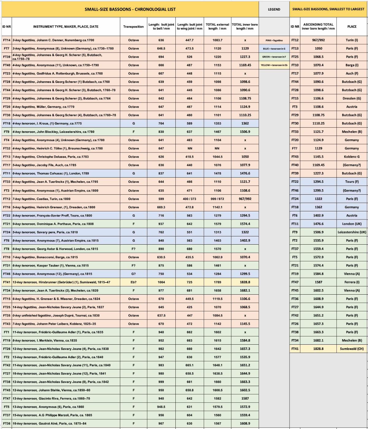
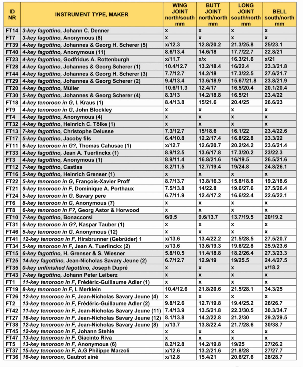
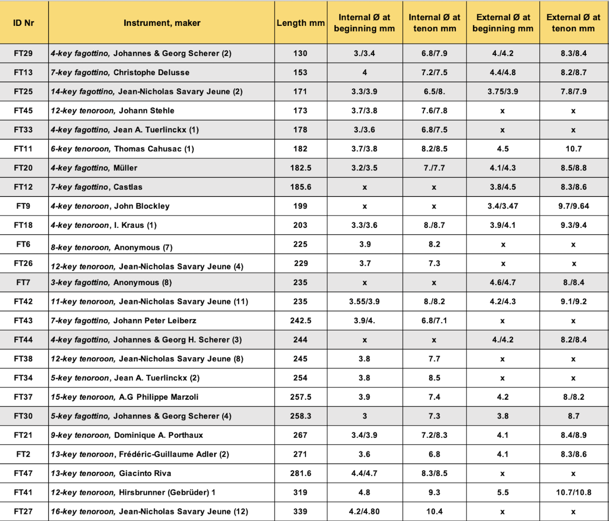
Collection and Comparisons of Measurement Data of Historical Small-Sized Bassoons

Veröffentlicht: 01.06.2023     Autor/in: Donna Agrell, Áurea Domínguez, Giovanni Battista Graziadio

Abstract

Two SNSF research projects hosted at the Schola Cantorum Basiliensis catalogued small-sized bassoons from the 18th and 19th centuries and investigated their musical and pedagogical roles. Additionally, reconstructions of four selected models combining 3D-CT technologies with conventional methods were undertaken. The detailed datasets, containing descriptions and measurements of the more than 60 small-sized bassoons examined, have been published in the open-access repository Zenodo and may be used to compare instrument types and aid in future reconstructions. In this article, manual methods and tools used to compile data are described, as well as various points of comparison.

Schlagwörter

fagottino, tenoroon, small-sized bassoons, manual measurements

Forschungsprojekt

Out of the Bass Register

Zitierweise

Donna Agrell, Áurea Domínguez, Giovanni Battista Graziadio, "Collection and Comparisons of Measurement Data of Historical Small-Sized Bassoons". Forschungsportal Schola Cantorum Basiliensis, 2023.
https://forschung.schola-cantorum-basiliensis.ch/de/forschung/out-of-bass-register/measurements-small-bassoons.html (Abgerufen am TT MM JJJJ)

Lizenz

The text of this article is provided under the terms of the Creative Commons License CC-BY-NC-ND 4.0

Figure 2: Bocal
Figure 3: Wing joint
Figure 4: Butt joint
Figure 5: Long joint
Figure 6: Bell
Figure 7: Everts' caliper set


Methods and tools for measuring internal bores

Everts’ caliper set

The set consists of a series of calipers ranging from 4.7 mm to 34 mm (the so-called fixed diameters) which can be perpendicularly screwed onto a ruler stick. [2] From 4.7 to 7.3 the calipers increase by 0.1 mm; from 7.4 mm to 25 mm, by 0.2 mm; from 25 mm to 34 mm, by 0.5 mm. The ruled stick with a fixed (preset) diameter is inserted into the instrument until it touches the wall of the bore, then L, which is the depth at that point, is measured.

Each measured value consists of two components: L, the depth (or distance) measured between the reference point R (end of instrument where measuring tool is inserted); and D, the diameter (Ø) at that point. L and D are perpendicular (Figure 8).

L minimum (Depth min.) and L maximum (Depth max.) are recorded for each fixed-diameter interval. (Woodwind bores tend to shrink over the years, resulting in cross sections having some degree of ovality.) [3] It is not required to find the maximum and minimum diameter at each point, but it is necessary to turn the instrument bore with extreme care while inserting the tool.


Figure 8: Components of depth and diameters, diagram from Bouterse 2015, Comm. 2032

The diameter progression inside the bore reflects these diameters steps as shown in Table 1.


The wing, long and butt big bore joints are measured from the smallest to largest diameter. Everts’ measuring tool is inserted into the bore from its largest diameter.


Values display an increasing series of diameters corresponding to a decreasing series of depths (see Table 1).


If it is not possible to uncork butt joint, the small bore cannot be measured with this tool; the series of rods cannot pass through the beginning of the bore, as the bore starts with its smallest diameter and expands down to the septum and cork space.


How can one measure the small bore in the butt joint?
In case uncorking is not possible, a tool inspired by David Rachor (Figure 9) has been made which enables measurements of the small bore of the butt joint to be taken. This tool is very similar to Everts’, the difference being that a tilted caliper can enter the bore, attached to the ruled stick with a flexible wire. When the bottom of the bore in the butt joint is reached, the wire is pulled so that the caliper leaves its tilted position and takes a perpendicular position on the ruler stick. Depths of diameter can thus be recorded. Using this tool, values will display in a decreasing series of diameters and a corresponding decreasing series of depths.

Figure 9: Tilting ruled caliper stick

If it is possible to remove the butt joint cork, then Everts’ measuring tool can be used to measure the small bore and data collected by inserting the tool through the cork space (south). Values will display the usual series of increasing diameters corresponding to a decreasing series of depths.

The bell is measured with Everts’ tool, starting from the southern part. The bell’s smallest diameter is usually found at the end of the northern part. If bells having an almost or very cylindrical bore are measured, two series of value sets can be offered: one measured from south to north and one measured from north to south, often with an irregular series of depths with big steps. Shrinking and/or ovality are more evident in these cases.


Some bells have an internal bell chamber right before its northern end. To measure this, the tilting caliper stick is employed by inserting it from north into the bell; value collection goes from south to north, that is: from the beginning of bell chamber to its end; values will display a decreasing series of depths and an irregular series of diameters (first increasing, then decreasing).


Diameters of tone holes

A set of cylinders are used to record the approximate diameter of tone holes. Cylinders are inserted into tone holes and the one fitting “snugly” is recorded as the approximate diameter. On the long joint, a digital caliper is often used instead of cylinders, especially for the D, C, and Bb tone holes.


Angles of tone holes

A special tool was designed for this purpose, as shown in Figure 10.

Figure 10: Framework with padded sticks to hold joint horizontally
Figure 11: Protractor

Each tone hole angle is measured using a protractor while the joint is attached to this framework. Each joint has an imaginary line passing through the center of its bore, aligned with the device and parallel to the surface of working surface. Joints are rotated to have an imaginary surface cutting the tone hole in two (theoretically equal) parts along its own axis. This imaginary surface must be perpendicular to the working surface. A padded stick centered in the axis of each tone hole is used to determine the angle and the angle of incidence between two imaginary lines is measured. The first imaginary line, coinciding with the stick going into the tone hole, extends down to the working surface; the second (perpendicular to the working surface at the point of incidence) is measured. (This last perpendicular line is called ‘normal’ in geometry, and it is at zero on the protractor.) Angle directions are indicated by “north” and “south”, according to the chimney direction into the bore.

Approximate lengths of tone holes

The approximate length of the axis of each tone hole, the segment starting in the center of the beginning of the tone hole and connecting to its end, is given. The small sliding measuring stick on digital calipers is used to measure these values, when possible. Alternatively, a wooden stick imaginarily connecting the centers of beginning and end of a tone hole is used: once aligned to the tone hole axis, this stick is positioned just before the beginning of the bore, and the start of the hole is marked by pencil, considering the instrument surface; the length between the pencil mark and the beginning of the stick gives the approximate length of the tone hole.

Comparison of bore diameters of single joints (smallest and largest diameters)

Table 3 gives rough information about how conicity is different or similar when considering bore diameters of joints of different instruments having similar lengths, approximating bores to regular conic sections and ignoring how the diameter progressions along the bores can vary. Using the values given in Table 3, more conjectures can be made if the instruments come from same region and/or period.

The volume of air put into vibration is what is significant for pitch/tone with instruments having similar bore lengths. This volume of each joint (and of the whole instrument) is directly proportional to the length of each joint, but it is even more proportional to the diameters of beginnings and ends of each bore. In any case, for more profound information of the design of bores, please consult our bore measurement collection in the instrument datasets on our project website.

Table 3: Comparison of bore diameters

Bocal lengths and diameters (shortest to longest)

A large range of bocal dimensions is displayed of those located with the examined small-sized bassoons in Table 4. It is impossible to confirm if all bocals have remained with the instruments they were built for (the only real test would be by playing), but of the three bocals located with Scherer fagottini, two are similar: FT44 (244 mm) and FT30 (258.3 mm). These kinds of comparisons can also be made with Savary Jeune bocals and others. An interesting investigation can be done by calculating the median of bocals located with different types of instruments.

Bocal and reed dimensions are complementary, influencing overall pitch, tuning, response, and tone quality. Reeds are generally chosen according to the individual player’s requirements and can therefore vary substantially. We have not located any original reeds for small-sized bassoons.

Fagottino: The shortest fagottino bocal belongs to FT29 Scherer (130 mm); the longest, to FT30 Scherer (258.3 mm). The “fagottino bocal median” calculated from all available fagottino bocal lengths (without any geographical or chronological ranking) is ca. 198 mm.

G tenoroon: There are only three bocals listed for G tenoroons: FT11 (182 mm), FT18 (203 mm), FT6 (225 mm). The “G tenoroon bocal median” calculated from all the available G tenoroon bocal lengths (without any geographical or chronological ranking) is ca. 203.333… mm, which can be approximated to the FT18 bocal length.

F tenoroon: The shortest F tenoroon bocal belongs to FT45 Stehle (173 mm); the longest, to FT27 Savary Jeune (339 mm). The “F tenoroon bocal median” calculated from all the available F tenoroon bocal lengths (without any geographical or chronological ranking) is ca. 252 mm.


Bocal Diameters

Fagottino: The median of the diameters at the beginning is 3.57 mm; the smallest diameter is 3 mm in FT30 Scherer, and largest is 4.35 mm in FT7. The median of the diameters at the tenon is 7.4 mm; the smallest is 6.95 mm (FT43 Leiberz) and largest is 7.95 mm (FT44 Scherer).

G tenoroon: The median of the diameters at the beginning 3.7 mm; the smallest diameter is 3.45 mm (FT18 Kraus) and largest is 3.9 mm (FT6 Anonymous). The median of the diameters at the tenon is 8.3 mm and is the same value (8.35 mm) for FT18 Kraus and FT11 Cahusac.

F tenoroon: The median of the diameters at the beginning is 3.93 mm; the smallest is 3.6 mm (FT2 Adler) and largest is 4.55 mm (FT47 Riva). The median of the diameters at the tenon is 8 mm; the smallest is 6.8 mm (FT2 Adler) and the largest is 10.4 mm (FT27 Savary Jeune).

Table 4: Bocal lengths and diameters
[1]

Baer 2018. The MUSICES project at the Germanisches Nationalmuseum developed scientific standards and guidelines recommending “optimized technical parameters of 3D-scanning, best practice recommendations for handling and scanning musical instruments, and outlines of a dedicated metadata model to stock and retrieve the accumulated information.”

[2]

This type of calipers is described in Bouterse 2015, Comm. 2032.

[3]

Ibid.